
拓扑图:
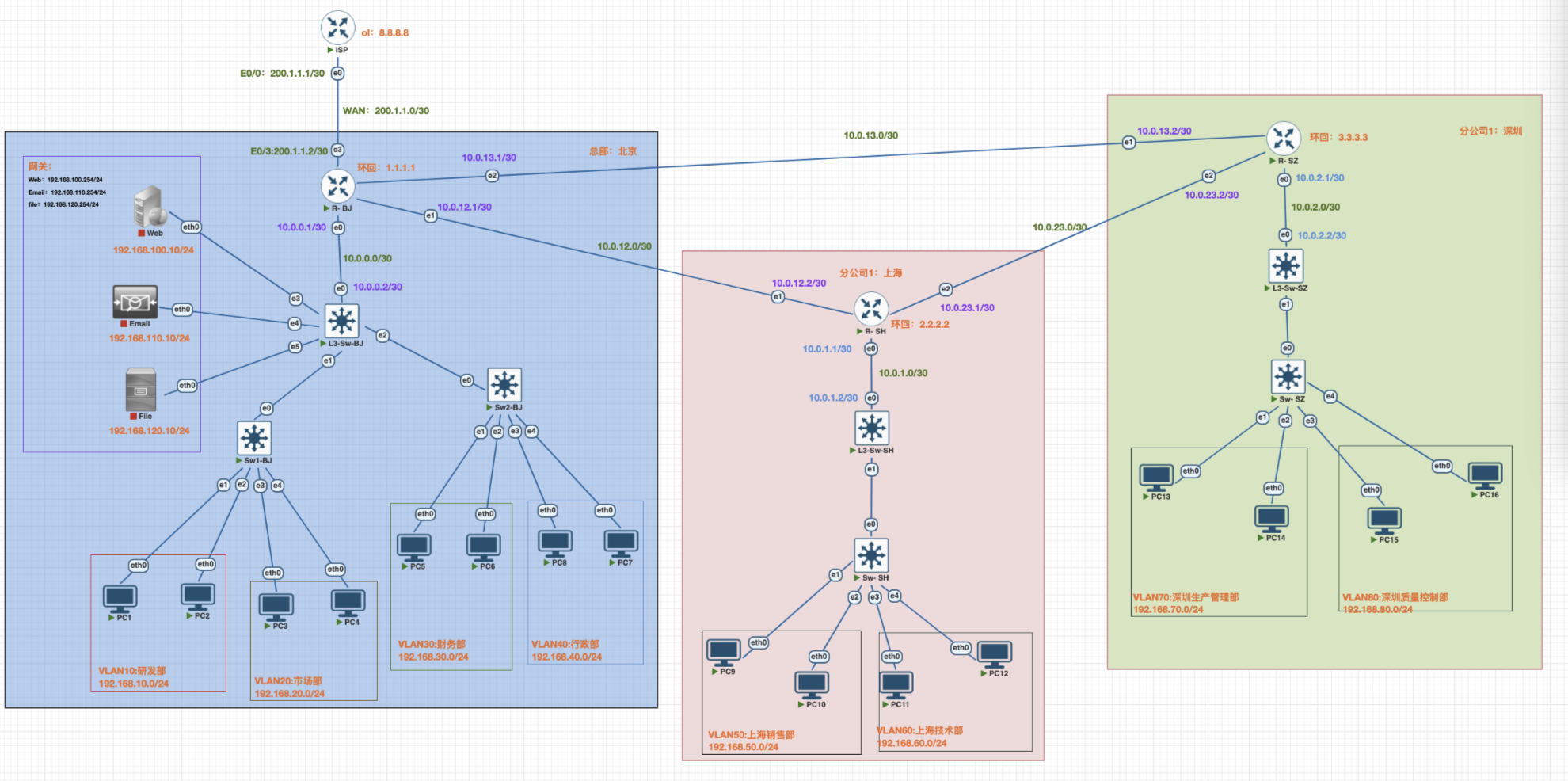
IP地址规划
网络搭建步骤
一.ISP路由配置
1.ISP上基本配置
enable # 进入特权模式
configure terminal # 进入全局配置模式
hostname ISP # 设置主机名为ISP
no ip domain-lookup # 关闭DNS查询 ,避免命令输入错误时的延迟
# 配置控制台
line console 0
exec-timeout 0 0 # 控制台永不超时( 实验环境)
logging synchronous # 日志信息不打断命令输入
exit
2配置Loopback接口模拟互联网(环回接口)
操作说明: 创建环回接口模拟互联网DNS服务器(8.8.8.8)
interface loopback 0
description Simulated Internet # 接口描述
ip address 8.8.8.8 255.255.255.0 # 配置IP地址 ,模拟公网DNS服务器
no shutdown # 启用接口 ( Loopback默认up ,但建议显式配置)
exit //退出
loopback(回环、环回)作用:
本地服务测试:当设备运行本地服务(如 Web 服务器、数据库)时,可通过 loopback 地址访问,无需配置真实网络
网络协议栈自:用于验证操作系统的网络协议栈是否正常工作:执行
ping 127.0.0.1,若能收到回复,说明本机的 TCP/IP 协议栈(网络驱动、内核网络模块)正常;若失败,可能是协议栈损坏或被禁用安全隔离部分服务(如敏感的管理接口)可配置为仅监听 loopback 地址,确保只能在本机访问,外部网络无法连接,降低被攻击风险。
3配置WAN接口连接到R-BJ路由器上
interface gigabitEthernet 0/0
description WAN Link to R-BJ # 接口描述
ip address 200.1.1.1 255.255.255.252 # 配置WAN链路IP(/30网络)
no shutdown
exit
4配置静态路由 ,指向内网
操作说明:配置访问路由,使内网可以收到回复数据包
ip route 192.168.0.0 255.255.0.0 200.1.1.2
说明:
- 目标网络: 192.168.0.0/16 (包含所有192.168.x.x网段)
- 下一跳: 200.1.1.2 (R- BJ的WAN接口)
- 这条路由确保ISP知道如何到达内网
end # 退出到特权模式
write memory # 保存配置到NVRAM
二.边界路由器基本配置
1.北京、上海、深圳边界路由器基本配置
enable # 进入特权模式
configure terminal # 进入全局配置模式
hostname R-XX # 设置主机名为R-xx
no ip domain-lookup # 关闭DNS查询 ,避免命令输入错误时的延迟
# 配置控制台
line console 0
exec-timeout 0 0 # 控制台永不超时( 实验环境)
logging synchronous # 日志信息不打断命令输入
exit
2.环回配置北京、上海、深圳路由器
配置Loopback接⼝
! 配置北京Loopback 0接⼝ ( ⽤作Router ID)
R-BJ(config)# interface loopback 0
R- BJ(config-if)# description Router ID
R-BJ(config-if)# ip address 1.1.1.1 255.255.255.255
R-BJ(config-if)# exit
! 配置上海Loopback 0接⼝ ( ⽤作Router ID)
R- SH(config)# interface loopback 0
R- SH(config-if)# description Router ID
R- SH(config-if)# ip address 2.2.2.2 255.255.255.255
R- SH(config-if)# exit
! 配置深圳Loopback 0接⼝ ( ⽤作Router ID)
R- SZ(config)# interface loopback 0
R- SZ(config-if)# description Router ID
R- SZ(config-if)# ip address 3.3.3.3 255.255.255.255
R- SZ(config-if)# exit
3 配置边界路由器物理接⼝
物理接口作用:
核心作用:连接物理网络,实现信号转换
物理接口的本质是 “硬件与网络的桥梁”,主要完成两个关键任务:
1.物理连接:通过对应的接口形态(如网线接口、光纤接口),直接对接外部传输介质(网线、光纤、天线),确保设备能接入物理网络。
2.信号转换:将设备内部的 “数字信号”(二进制数据)转换为适合物理介质传输的 “模拟信号”(如网线的电信号、光纤的光信号、无线的电磁波信号),同时接收外部传来的模拟信号,再转换为数字信号供设备处理
3.1.R- BJ路由器物理接口
! 配置e0/0接⼝ (连接北京L3-SW-BJ)
R- BJ(config)# interface ethernet 0/0
R-BJ(config-if)# description Link to L3-SW-BJ
R-BJ(config-if)# ip address 10.0.0.1 255.255.255.252
R-BJ(config-if)# no shutdown
R-BJ(config-if)# exit
! 配置e0/1接⼝ (连接上海R- SH)
R- BJ(config)# interface ethernet 0/1
R- BJ(config-if)# description WAN to SH
R- BJ(config-if)# ip address 10.0.12.1 255.255.255.252
R- BJ(config-if)# no shutdown
R- BJ(config-if)# exit
! 配置e0/2接⼝ (连接深圳R-SZ)
R- BJconfig)# interface ethernet 0/3
R- BJ(config-if)# description WAN to SZ
R- BJ(config-if)# ip address 10.0.13.1 255.255.255.252
R- BJ(config-if)# no shutdown
R- BJ(config-if)# exit
# 配置WAN接口 ( 边界路由接口)
interface gigabitEthernet 0/3
description WAN Link ISP # 接口描述
ip address 200.1.1.2 255.255.255.252 # 配置WAN链路IP
no shutdown
exit
3.2.R- SH路由器物理接口
! 配置e0/0接⼝ (连接北京L3-SW-SH)
R- SH(config)# interface ethernet 0/0
R- SH(config-if)# description Link to L3-SW-SH
R- SH(config-if)# ip address 10.0.1.1 255.255.255.255
R-SH(config-if)# no shutdown
R-SH(config-if)# exit
! 配置e0/1接⼝ (连接北京R- BJ)
R- SH(config)# interface ethernet 0/1
R- SH(config-if)# description WAN to BJ
R- SH(config-if)# ip address 10.0.12.2 255.255.255.255
R- SH(config-if)# no shutdown
R- SH(config-if)# exit
! 配置e0/2接⼝ (连接深圳R-SZ)
R-SHconfig)# interface ethernet 0/2
R-SH(config-if)# description WAN to SZ
R-SH(config-if)# ip address 10.0.23.1 255.255.255.255
R-SH(config-if)# no shutdown
R-SH(config-if)# exit
3.3.R- SZ路由器物理接口
! 配置e0/0接⼝ (连接深圳L3-SW-SZ)
R- SZ(config)# interface ethernet 0/0
R- SZ(config-if)# description Link to L3-SW-SZ
R- SZ(config-if)# ip address 10.0.2.1 255.255.255.255
R-SZ(config-if)# no shutdown
R-SZ(config-if)# exit
! 配置e0/1接⼝ (连接北京R- BJ)
R- SZ(config)# interface ethernet 0/1
R- SZ(config-if)# description WAN to BJ
R- SZ(config-if)# ip address 10.0.13.2 255.255.255.255
R- SZ(config-if)# no shutdown
R- SZ(config-if)# exit
! 配置e0/2接⼝ (连接上海R- SH)
R- SZconfig)# interface ethernet 0/2
R- SZ(config-if)# description WAN to SZ
R- SZ(config-if)# ip address 10.0.23.2 255.255.255.255
R- SZ(config-if)# no shutdown
R- SZ(config-if)# exit
4 配置边界路由器OSPF
!OSPF作用:
OSPF是动态路由协议:用于在 IP 网络中自动计算和维护路由信息,核心作用是让路由器之间 “自动学习” 网络拓扑,动态生成最优路径,确保数据高效、可靠地在大型网络中传输。
“区域划分”,优化大型网络性能:将网络划分为多个区域(如 Area 0 为骨干区域,其他为非骨干区域),非骨干区域仅需向骨干区域发送汇总后的 LSA,减少数据交换量。骨干区域负责区域间的路由传递,确保区域间通信的同时,降低单台路由器的计算负担
4.1 北京OSPF配置
! 启⽤OSPF进程1
R-BJ(config)# router ospf 1
! 配置北京Router ID
R-BJ(config-router)# router-id 1.1.1.1
! 宣告北京⽹络到Area 0( 骨⼲区域)
R-BJ(config-router)# network 10.0.0.0 0.0.0.3 area 0
R-BJ(config-router)# network 10.0.1.0 0.0.0.3 area 0
R-BJ(config-router)# network 10.0.12.0 0.0.0.3 area 0
R-BJ(config-router)# network 10.0.13.0 0.0.0.3 area 0
R-BJ(config-router)# network 1.1.1.1 0.0.0.0 area 0
! 退出OSPF配置
R-SH(config-router)# exit
4.2上海OSPF配置
! 启⽤OSPF进程1
R-SH(config)# router ospf 1
! 配置上海Router ID
R-SH(config-router)# router-id 2.2.2.2
! 宣告上海⽹络到Area 0( 骨⼲区域)
R-SH(config-router)# network 10.0.1.0 0.0.0.3 area 0
R-SH(config-router)# network 10.0.23.0 0.0.0.3 area 0
R-SH(config-router)# network 10.0.12.0 0.0.0.3 area 0
R-SH(config-router)# network 2.2.2.2 0.0.0.0 area 0
! 退出OSPF配置
R-SH(config-router)# exit
4.3深圳OSPF配置
! 启⽤OSPF进程1
R-SZ(config)# router ospf 1
! 配置深圳Router ID
R-SZ(config-router)# router-id 3.3.3.3
! 宣告上深圳络到Area 0( 骨⼲区域)
R-SZ(config-router)# network 10.0.2.0 0.0.0.3 area 0
R-SZ(config-router)# network 10.0.23.0 0.0.0.3 area 0
R-SZ(config-router)# network 10.0.13.0 0.0.0.3 area 0
R-SZ(config-router)# network 3.3.3.3 0.0.0.0 area 0
! 退出OSPF配置
R-SZ(config-router)# exit
配置作⽤总结:
. 比如将R—BJ作为OSPF骨⼲区域(Area 0) 的核⼼路由器
. 建⽴与其他路由器的OSPF邻居关系
. 通过OSPF⾃动学习和分发路由信息
. 实现整个⽹络的动态路由功能
5.配置NAT(地址转换)
在R- BJ上配置NAT转换(配置的一定是连接外网的路由器或者三层交换机)
配置说明: 配置PAT(端口地址转换),使内网和DMZ可以通过单个公网IP访问互联网。
L3-SW# configure terminal #给予特权
5.1创建标准ACL定义允许NAT的网络
R-BJ(config)# access-list 1 remark NAT Allowed Networks # ACL注释
R-BJ(config)# access-list 1 permit 192.168.10.0 0.0.0.255 # 允许VLAN 10 (研发部)
R-BJ(config)# access-list 1 permit 192.168.20.0 0.0.0.255 # 允许VLAN 20 (市场部)
R-BJ(config)# access-list 1 permit 192.168.30.0 0.0.0.255 # 允许VLAN 30 (财务部)
R-BJ(config)# access-list 1 permit 192.168.40.0 0.0.0.255 # 允许VLAN 40 (行政部)
R-BJ(config)# access-list 1 permit 192.168.50.0 0.0.0.255 # 允许VLAN 50 (销售部)
R-BJ(config)# access-list 1 permit 192.168.60.0 0.0.0.255 # 允许VLAN 60 (技术部)
R-BJ(config)# access-list 1 permit 192.168.70.0 0.0.0.255 # 允许VLAN 70 (生产管理部)
R-BJ(config)# access-list 1 permit 192.168.80.0 0.0.0.255 # 允许VLAN 80 (质量控制部)
L3-SW-BJ(config)# access-list 1 permit 192.168.100.0 0.0.0.255 # 允许DMZ(Web)区域
L3-SW-BJ(config)# access-list 1 permit 192.168.110.0 0.0.0.255 # 允许DMZ(Email)区域
L3-SW-BJ(config)# access-list 1 permit 192.168.120.0 0.0.0.255 # 允许DMZ(File)区域
5.2配置NAT内部接口 (所有内网和DMZ接口)
R-BJ(config)# interface vlan 10
R-BJ(config-if)# ip nat inside # 标记为NAT内部接口
R-BJ(config-if)# exit
R-BJ(config)# interface vlan 20
R-BJ(config-if)# ip nat inside # 标记为NAT内部接口
R-BJ(config-if)# exit
R-BJ(config)# interface vlan 30
R-BJ(config-if)# ip nat inside # 标记为NAT内部接口
R-BJ(config-if)# exit
R-BJ(config)# interface vlan 40
R-BJ(config-if)# ip nat inside # 标记为NAT内部接口
R-BJ(config-if)# exit
R-BJ(config)# interface vlan 50
R-BJ(config-if)# ip nat inside # 标记为NAT内部接口
R-BJ(config-if)# exit
R-BJ(config)# interface vlan 60
R-BJ(config-if)# ip nat inside # 标记为NAT内部接口
R-BJ(config-if)# exit
R-BJ(config)# interface vlan 70
R-BJ(config-if)# ip nat inside # 标记为NAT内部接口
R-BJ(config-if)# exit
R-BJ(config)# interface vlan 80
R-BJ(config-if)# ip nat inside # 标记为NAT内部接口
R-BJ(config-if)# exit
R-BJ(config)# interface gigabitEthernet 0/3
R-BJ(config-if)# ip nat inside # DMZ(Web)接口标记为NAT内部
R-BJ(config-if)# exit
R-BJ(config)# interface gigabitEthernet 1/0
R-SW-BJ(config-if)# ip nat inside # DMZ(Email)接口标记为NAT内部
R-SW-BJ(config-if)# exit
R-BJ(config)# interface gigabitEthernet 1/1
R-BJ(config-if)# ip nat inside # DMZ(File)接口标记为NAT内部
R-BJ(config-if)# exit
5.3配置NAT外部接口 (WAN接口)
R- BJ(config)# interface gigabitEthernet 0/3
R- BJ(config-if)# ip nat outside # 标记为NAT外部接口
R- BJ(config-if)# exit
5.4 配置PAT(端口地址转换)
# overload关键字启用PAT ,允许多个内网地址共享一个公网IP
R-BJ(config)# ip nat inside source list 1 interface gigabitEthernet 0/3 over load
R-BJ(config)# end
R-BJ# write memory # 保存配置
6.在R- BJ上配置ACL
ACL作用说明:
核心作用:控制数据包的 “准入与拒绝”
ACL 通过定义 “允许哪些数据通过” 和 “禁止哪些数据通过”
网络安全防护(最核心作用)
阻止未授权访问:例如,禁止外部网络(如互联网)直接访问内网的敏感服务器(如数据库服务器
192.168.1.100),只允许内部部办公网段(192.168.1.0/24)访问。过滤恶意流量:拒绝来自部来源的特定端口流量(如禁止外部对端口 3389 的访问,防止远程桌面攻击;禁止端口 22 的异常 IP 访问,防御 SSH 暴力破解)。
2. 网络流量管理
限制特定服务的使用:例如,禁止内网设备访问外网的,避免占用过多带宽;只允许访问工作相关的 HTTP(80)和 HTTPS(443)端口。
隔离不同网段:在企业网络中,通过 ACL 限制财务网段(
192.168.30.0/24)与普通办公网段(192.168.10.0/24)的直接通信,仅允许通过指定服务器中转数据。
3. 精确控制路由与转发
在路由器上,ACL 可配合路由策略(如路由映射),只允许特定来源的路由信息被接收或发布,避免路由表被无效信息占用。
例如,仅接收来自信任邻居路由器(
10.0.0.1)的 OSPF 路由更新,拒绝其他来源的路由信息
(!根据自身需求区配置,以下只是举例)
#财务部访问控制(ACL 100)
L3-SW(config)# access-list 100 remark Finance Department Access Control
# 拒绝财务部访问研发部
L3-SW(config)# access-list 100 deny ip 192.168.30.0 0.0.0.255 192.168.10.0 0.0.0.255
# 拒绝财务部访问市场部
L3-SW(config)# access-list 100 deny ip 192.168.30.0 0.0.0.255 192.168.20.0 0.0.0.255
# 允许财务部访问其他所有网络(包括DMZ和互联网)
L3-SW(config)# access-list 100 permit ip 192.168.30.0 0.0.0.255 any
# 研发部访问控制(ACL 110)
L3-SW(config)# access-list 110 remark R&D Department Access Control
# 拒绝研发部访问财务部
L3-SW(config)# access-list 110 deny ip 192.168.10.0 0.0.0.255 192.168.30.0 0.0.0.255
# 拒绝研发部访问DMZ
L3-SW(config)# access-list 110 deny ip 192.168.10.0 0.0.0.255 192.168.100.0 0.0.0.255
# 允许研发部访问其他所有网络(市场部和互联网)
L3-SW(config)# access-list 110 permit ip 192.168.10.0 0.0.0.255 any
#市场部访问控制(ACL 115)
L3-SW(config)# access-list 115 remark Marketing Department Access Control
# 拒绝市场部访问财务部
L3-SW(config)# access-list 115 deny ip 192.168.20.0 0.0.0.255 192.168.30.0 0.0.0.255
# 拒绝市场部访问DMZ
L3-SW(config)# access-list 115 deny ip 192.168.20.0 0.0.0.255 192.168.100.0 0.0.0.255
# 允许市场部访问其他所有网络(研发部和互联网)
L3-SW(config)# access-list 115 permit ip 192.168.20.0 0.0.0.255 any
# DMZ访问控制(ACL 120)
# 这是最关键的配置 ,实现单向访问控制
L3-SW(config)# access-list 120 remark DMZ Access Control
# 拒绝DMZ主动访问研发部
L3-SW(config)# access-list 120 deny ip 192.168.100.0 0.0.0.255 192.168.10.0 0.0.0.255
# 拒绝DMZ主动访问市场部
L3-SW(config)# access-list 120 deny ip 192.168.100.0 0.0.0.255 192.168.20.0 0.0.0.255
# 允许DMZ响应财务部的TCP连接(established关键字)
L3-SW(config)# access-list 120 permit tcp 192.168.100.0 0.0.0.255 192.168.30.0 0.0.0.255 established
# 允许DMZ响应财务部的ping请求(echo-reply)
L3-SW(config)# access-list 120 permit icmp 192.168.100.0 0.0.0.255 192.16 8.30.0 0.0.0.255 echo-reply
# 允许DMZ响应财务部的UDP会话
L3-SW(config)# access-list 120 permit udp 192.168.100.0 0.0.0.255 192.168.30.0 0.0.0.255
# 明确拒绝DMZ主动发起到财务部的其他连接
L3-SW(config)# access-list 120 deny ip 192.168.100.0 0.0.0.255 192.168.30.0 0.0.0.255
# 允许DMZ访问互联网
L3-SW(config)# access-list 120 permit ip 192.168.100.0 0.0.0.255 any
6.1将ACL应用到接口
# 应用ACL 110到VLAN 10入站方向(控制从研发部发出的流量)
L3-SW(config)# interface vlan 10
L3-SW(config-if)# ip access-group 110 in
L3-SW(config-if)# exit
# 应用ACL 115到VLAN 20入站方向(控制从市场部发出的流量)
L3-SW(config)# interface vIan 20
L3-SW(config-if)# ip access-group 115 in
L3-SW(config-if)# exit
# 应用ACL 100到VLAN 30入站方向(控制从财务部发出的流量)
L3-SW(config)# interface vIan 30
L3-SW(config-if)# ip access-group 100 in
L3-SW(config-if)# exit
# 应用ACL 120到Gi0/3入站方向(控制从DMZ发出的流量)
L3-SW(config)# interface gigabitEthernet 0/3
L3-SW(config-if)# ip access-group 120 in
L3-SW(config-if)# exit
L3-SW(config)# end
L3-SW# write memory
三、L3-SW三层交换机配置
1.北京、上海、深圳三层交换机基本配置
enable # 进入特权模式
configure terminal # 进入全局配置模式
hostname ISP # 设置主机名为ISP
no ip domain-lookup # 关闭DNS查询 ,避免命令输入错误时的延迟
# 配置控制台
line console 0
exec-timeout 0 0 # 控制台永不超时( 实验环境)
logging synchronous # 日志信息不打断命令输入
exit
2.三层交换机VLAN创建
2.1.北京L3-SW-BJ创建
vlan 10
name RD
exit
vlan 20
name MAR
exit
vlan 30
name FIN
exit
vlan 40
name XZ
exit
2.2.上海L3-SW-SH创建
vlan 50
name XS
exit
vlan 60
name JS
exit
2.3.深圳L3-SW-SZ创建
vlan 60
name SCXS
exit
vlan 60
name ZLKZ
exit
3.配置Trunk接口
3.1.北京(L3-SW-BJ)Trunk接口到SW1-BJ
interface gigabitEthernet 0/1
description Trunk to SW1 # 接口描述
switchport trunk encapsulation dot1q # 封装协议802.1Q
switchport mode trunk # 设置为Trunk模式
switchport trunk allowed vlan 10,20, # 只允许VLAN 10,20,通过
no shutdown
exit
配置Trunk接口到SW2-BJ
interface gigabitEthernet 0/2
description Trunk to SW2 # 接口描述
switchport trunk encapsulation dot1q # 封装协议802.1Q
switchport mode trunk # 设置为Trunk模式
switchport trunk allowed vlan 30,40 # 只允许VLAN 30,40通过
no shutdown
exit
# 配置边界路由接口
interface gigabitEthernet 0/0
description WAN Link to R- BJ # 接口描述
no switchport # 将接口从二层模式切换到三层模式
ip address 10.0.0.2 255.255.255.252 # 配置WAN链路IP
no shutdown
exit
# 配置DMZ接口 ( Web)
interface gigabitEthernet 0/3
description DMZ Zone - Web Server # 接口描述
no switchport # 切换到三层模式
ip address 192.168.100.254 255.255.255.0 # 配置DMZ网关IP
no shutdown
exit
# 配置DMZ接口 ( Email)
interface gigabitEthernet 1/0
description DMZ Zone - Email Server # 接口描述
no switchport # 切换到三层模式
ip address 192.168.110.254 255.255.255.0 # 配置DMZ网关IP
no shutdown
exit
# 配置DMZ接口 ( File)
interface gigabitEthernet 1/1
description DMZ Zone - File Server # 接口描述
no switchport # 切换到三层模式
ip address 192.168.120.254 255.255.255.0 # 配置DMZ网关IP
no shutdown
exit
# 配置VLAN 10的SVI(交换虚拟接口)
interface vlan 10
description Gateway for RD # 接口描述
ip address 192.168.10.254 255.255.255.0 # 配置网关IP
no shutdown # 启用接口 (SVI默认shutdown)
exit
# 配置VLAN 20的SVI
interface vlan 20
description Gateway for Mar
ip address 192.168.20.254 255.255.255.0
no shutdown
exit
# 配置VLAN 30的SVI
interface vlan 30
description Gateway for Fin
ip address 192.168.30.254 255.255.255.0
no shutdown
exit
# 配置VLAN 40的SVI
interface vlan 40
description Gateway for Fin
ip address 192.168.30.254 255.255.255.0
no shutdown
exit
# 配置默认路由指向R-BJ
ip route 0.0.0.0 0.0.0.0 10.0.0.1 # 所有未知流量转发到R-BJ路由器
3.2.上海(L3-SW-上海)Trunk接口到SW-SH
interface gigabitEthernet 0/1
description Trunk to SW- SH # 接口描述
switchport trunk encapsulation dot1q # 封装协议802.1Q
switchport mode trunk # 设置为Trunk模式
switchport trunk allowed vlan 50,60, # 只允许VLAN 50,60,通过
no shutdown
exit
# 配置上海边界路由接口
interface gigabitEthernet 0/0
description WAN Link to R-SH # 接口描述
no switchport # 将接口从二层模式切换到三层模式
ip address 10.0.1.2 255.255.255.252 # 配置链路IP
no shutdown
exit
# 配置VLAN 50的SVI(交换虚拟接口)
interface vlan 50
description Gateway for XS # 接口描述
ip address 192.168.50.254 255.255.255.0 # 配置网关IP
no shutdown # 启用接口 (SVI默认shutdown)
exit
# 配置VLAN 60的SVI
interface vlan 60
description Gateway for JS
ip address 192.168.60.254 255.255.255.0
no shutdown
exit
# 配置默认路由指向R-SH
ip route 0.0.0.0 0.0.0.0 10.0.1.1 # 所有未知流量转发到R-SH路由器
3.3.深圳(L3-SW-SZ)Trunk接口到SW-SZ
interface gigabitEthernet 0/1
description Trunk to SW- SZ # 接口描述
switchport trunk encapsulation dot1q # 封装协议802.1Q
switchport mode trunk # 设置为Trunk模式
switchport trunk allowed vlan 70,80, # 只允许VLAN 70,80,通过
no shutdown
exit
# 配置上海边界路由接口
interface gigabitEthernet 0/0
description WAN Link to R-SZ # 接口描述
no switchport # 将接口从二层模式切换到三层模式
ip address 10.0.2.2 255.255.255.252 # 配置链路IP
no shutdown
exit
# 配置VLAN 70的SVI(交换虚拟接口)
interface vlan 70
description Gateway for SCGL # 接口描述
ip address 192.168.70.254 255.255.255.0 # 配置网关IP
no shutdown # 启用接口 (SVI默认shutdown)
exit
# 配置VLAN 80的SVI
interface vlan 70
description Gateway for ZLXS
ip address 192.168.80.254 255.255.255.0
no shutdown
exit
# 配置默认路由指向R-SH
ip route 0.0.0.0 0.0.0.0 10.0.2.1 # 所有未知流量转发到R-SH路由器
4.配置DHPC地址分配
优势:
集中管理: 统一管理IP地址分配
自动配置: 无需手动配置客户端
减少错误: 避免IP地址冲突和配置错误
灵活调整: 便于网络参数变更
地址复用: 提高IP地址利用率
缺陷:
单点故障: DHCP服务器故障影响全网
安全风险: 可能遭受DHCP欺骗攻击
网络依赖: 需要网络连通才能获取地址
不适合服务器: 服务器需要固定IP
4.1.在北京(L3-SW-BJ)上配置
! 启⽤三层交换功能
L3-SW(config)# ip routing
! 排除VLAN 10的保留地址
L3-SW(config)# ip dhcp excluded-address 192.168.10.1 192.168.10.9
L3-SW(config)# ip dhcp excluded-address 192.168.10.254
! 排除VLAN 20的保留地址
L3-SW(config)# ip dhcp excluded-address 192.168.20.1 192.168.20.9
L3-SW(config)# ip dhcp excluded-address 192.168.20.254
! 排除VLAN 30的保留地址
L3-SW(config)# ip dhcp excluded-address 192.168.30.1 192.168.30.9
L3-SW(config)# ip dhcp excluded-address 192.168.30.254
! 排除VLAN 40的保留地址
L3-SW(config)# ip dhcp excluded-address 192.168.40.1 192.168.30.9
L3-SW(config)# ip dhcp excluded-address 192.168.40.254
! 创建VLAN 10的DHCP地址池
L3-SW(config)# ip dhcp pool VLAN10
L3-SW(dhcp-config)# network 192.168.10.0 255.255.255.0
L3-SW(dhcp-config)# default-router 192.168.10.254
L3-SW(dhcp-config)# dns-server 8.8.8.8 114.114.114.114
L3-SW(dhcp-config)# domain-name rd.yxwa.com
L3-SW(dhcp-config)# lease 7
L3-SW(dhcp-config)# exit
! 创建VLAN 20的DHCP地址池
L3-SW(config)# ip dhcp pool VLAN20
L3-SW(dhcp-config)# network 192.168.20.0 255.255.255.0
L3-SW(dhcp-config)# default-router 192.168.20.254
L3-SW(dhcp-config)# dns-server 8.8.8.8 114.114.114.114
L3-SW(dhcp-config)# domain-name mark.yxwa.com
L3-SW(dhcp-config)# lease 7
L3-SW(dhcp-config)# exit
! 创建VLAN 30的DHCP地址池
L3-SW(config)# ip dhcp pool VLAN30
L3-SW(dhcp-config)# network 192.168.30.0 255.255.255.0
L3-SW(dhcp-config)# default-router 192.168.30.254
L3-SW(dhcp-config)# dns-server 8.8.8.8 114.114.114.114
L3-SW(dhcp-config)# domain-name fin.yxwa.com
L3-SW(dhcp-config)# lease 7
L3-SW(dhcp-config)# exit
! 创建VLAN 40的DHCP地址池
L3-SW(config)# ip dhcp pool VLAN40
L3-SW(dhcp-config)# network 192.168.40.0 255.255.255.0
L3-SW(dhcp-config)# default-router 192.168.40.254
L3-SW(dhcp-config)# dns-server 8.8.8.8 114.114.114.114
L3-SW(dhcp-config)# domain-name XZ.yxwa.com
L3-SW(dhcp-config)# lease 7
L3-SW(dhcp-config)# exit
! 全局启⽤DHCP服务(默认已启⽤)
L3-SW(config)# service dhcp
命令解释:
- ip dhcp pool VLAN10 : 创建名为VLAN10的地址池
- network : 指定⽹络地址和⼦⽹掩码
- default-router : 指定默认⽹关
- dns-server : 指定DNS服务器(可以配置多个)
- domain-name : 指定域名
- lease 7 : 设置租约为7天
4.2.在上海(L3-SW-SH)上配置
! 启⽤三层交换功能
L3-SW(config)# ip routing
! 排除VLAN 50的保留地址
L3-SW(config)# ip dhcp excluded-address 192.168.50.1 192.168.50.9
L3-SW(config)# ip dhcp excluded-address 192.168.50.254
! 排除VLAN 60的保留地址
L3-SW(config)# ip dhcp excluded-address 192.168.60.1 192.168.60.9
L3-SW(config)# ip dhcp excluded-address 192.168.60.254
! 创建VLAN 50的DHCP地址池
L3-SW(config)# ip dhcp pool VLAN50
L3-SW(dhcp-config)# network 192.168.50.0 255.255.255.0
L3-SW(dhcp-config)# default-router 192.168.50.254
L3-SW(dhcp-config)# dns-server 8.8.8.8 114.114.114.114
L3-SW(dhcp-config)# domain-name XS.yxwa.com
L3-SW(dhcp-config)# lease 7
L3-SW(dhcp-config)# exit
! 创建VLAN 60的DHCP地址池
L3-SW(config)# ip dhcp pool VLAN60
L3-SW(dhcp-config)# network 192.168.60.0 255.255.255.0
L3-SW(dhcp-config)# default-router 192.168.60.254
L3-SW(dhcp-config)# dns-server 8.8.8.8 114.114.114.114
L3-SW(dhcp-config)# domain-name JS.yxwa.com
L3-SW(dhcp-config)# lease 7
L3-SW(dhcp-config)# exit
! 全局启⽤DHCP服务(默认已启⽤)
L3-SW(config)# service dhcp
4.3.在深圳(L3-SW-SZ)上配置
! 启⽤三层交换功能
L3-SW(config)# ip routing
! 排除VLAN 70的保留地址
L3-SW(config)# ip dhcp excluded-address 192.168.70.1 192.168.70.9
L3-SW(config)# ip dhcp excluded-address 192.168.70.254
! 排除VLAN 80的保留地址
L3-SW(config)# ip dhcp excluded-address 192.168.80.1 192.168.80.9
L3-SW(config)# ip dhcp excluded-address 192.168.80.254
! 创建VLAN 70的DHCP地址池
L3-SW(config)# ip dhcp pool VLAN70
L3-SW(dhcp-config)# network 192.168.70.0 255.255.255.0
L3-SW(dhcp-config)# default-router 192.168.70.254
L3-SW(dhcp-config)# dns-server 8.8.8.8 114.114.114.114
L3-SW(dhcp-config)# domain-name SCGL.yxwa.com
L3-SW(dhcp-config)# lease 7
L3-SW(dhcp-config)# exit
! 创建VLAN 80的DHCP地址池
L3-SW(config)# ip dhcp pool VLAN80
L3-SW(dhcp-config)# network 192.168.80.0 255.255.255.0
L3-SW(dhcp-config)# default-router 192.168.80.254
L3-SW(dhcp-config)# dns-server 8.8.8.8 114.114.114.114
L3-SW(dhcp-config)# domain-name ZLKZ.yxwa.com
L3-SW(dhcp-config)# lease 7
L3-SW(dhcp-config)# exit
! 全局启⽤DHCP服务(默认已启⽤)
L3-SW(config)# service dhcp
四.SW接入交换机配置
配置说明: SW1-BJ是接入层交换机 ,连接PC1、 PC2、 PC3、PC4
1.北京SW1- BJ基本配置
enable # 进入特权模式
configure terminal # 进入全局配置模式
hostname SW1 # 设置主机名
no ip domain-lookup # 关闭DNS查询
line console 0
exec-timeout 0 0 # 控制台永不超时
logging synchronous # 日志同步显⽰
exit
end # 退出到特权模式
write memory # 保存配置
# 创建VLAN(必须与L3-SW-BJ—致)
vlan 10
name R&D # VLAN 10: 研发部
exit
vlan 20
name MAR # VLAN 20 :市场部
exit
# 配置Trunk接口到L3-SW-BJ
interface gigabitEthernet 0/0
description Trunk to L3-SW-BJ # 接口描述
switchport trunk encapsulation dot1q # 封装协议802.1Q
switchport mode trunk # 设置为Trunk模式
switchport trunk allowed vlan 10,20 # 允许VLAN 10,20通过
no shutdown
exit
# 配置Access接口到PC1(VLAN 10)
interface gigabitEthernet 0/1
description Access to PC1 # 接口描述
switchport mode access # 设置为Access模式
switchport access vlan 10 # 分配到VLAN 10
spanning-tree portfast # 启用PortFast(端口快速转发 ,用于终端设备)
no shutdown
exit
# 配置Access接口到PC2(VLAN 10)
interface gigabitEthernet 0/2
description Access to PC2 # 接口描述
switchport mode access # 设置为Access模式
switchport access vlan 10 # 分配到VLAN 10
spanning-tree portfast # 启用PortFast
no shutdown
exit
# 配置Access接口到PC3(VLAN 20)
interface gigabitEthernet 0/3
description Access to PC3 # 接口描述
switchport mode access # 设置为Access模式
switchport access vlan 20 # 分配到VLAN 20
spanning-tree portfast # 启用PortFast
no shutdown
exit
配置Access接口到PC4(VLAN 20)
interface gigabitEthernet 1/0
description Access to PC3 # 接口描述
switchport mode access # 设置为Access模式
switchport access vlan 20 # 分配到VLAN 20
spanning-tree portfast # 启用PortFast
no shutdown
exit
北京SW2-BJ接入交换机配置
配置说明: SW2是接入层交换机 ,连接PC5、 PC6、 PC7、PC8
enable # 进入特权模式
configure terminal # 进入全局配置模式
hostname SW2-BJ # 设置主机名
no ip domain-lookup # 关闭DNS查询
line console 0
exec-timeout 0 0 # 控制台永不超时
logging synchronous # 日志同步显⽰
exit
end # 退出到特权模式
write memory # 保存配置
# 创建VLAN(只创建SW2需要的VLAN)
vlan 30
name FIN # VLAN 30 :财务部
exit
vlan 40
name XZ # VLAN 40: 行政部
exit
# 配置Trunk接口到L3-SW-BJ
interface gigabitEthernet 0/0
description Trunk to L3-SW - BJ # 接口描述
switchport trunk encapsulation dot1q # 封装协议802.1Q switchport mode trunk # 设置为Trunk模式
switchport trunk allowed vlan 30,40 # 只允许VLAN 40,30通过
no shutdown
exit
# 配置Access接口到PC5(VLAN 30)
interface gigabitEthernet 0/1
description Access to PC5 # 接口描述
switchport mode access # 设置为Access模式switchport access vlan 30
spanning-tree portfast # 启用PortFast
no shutdown
exit
# 配置Access接口到PC6(VLAN 30)
interface gigabitEthernet 0/2
description Access to PC6 # 接口描述
switchport mode access # 设置为Access模式switchport access vlan 30
spanning-tree portfast # 启用PortFast no shutdown
exit
# 配置Access接口到PC7(VLAN 40)
interface gigabitEthernet 0/3
description Access to PC7 # 接口描述
switchport mode access # 设置为Access模式switchport access vlan 40
spanning-tree portfast # 启用PortFast no shutdown
exit
# 配置Access接口到PC8(VLAN 40)
interface gigabitEthernet 1/0
description Access to PC8 # 接口描述
switchport mode access # 设置为Access模式switchport access vlan 40
spanning-tree portfast # 启用PortFast no shutdown
exit
上海SW-SH接入交换机配置
enable # 进入特权模式
configure terminal # 进入全局配置模式
hostname SW-SH # 设置主机名
no ip domain-lookup # 关闭DNS查询
line console 0
exec-timeout 0 0 # 控制台永不超时
logging synchronous # 日志同步显⽰
exit
end # 退出到特权模式
write memory # 保存配置
# 创建VLAN(必须与L3-SW-SH)
vlan 50
name XS # VLAN 50: 销售部
exit
vlan 60
name JS # VLAN 60 :技术部
exit
# 配置Trunk接口到L3-SW
interface gigabitEthernet 0/0
description Trunk to L3-SW—SH # 接口描述
switchport trunk encapsulation dot1q # 封装协议802.1Q
switchport mode trunk # 设置为Trunk模式
switchport trunk allowed vlan 50,60
no shutdown
exit
# 配置Access接口到PC9(VLAN 50)
interface gigabitEthernet 0/1
description Access to PC9 # 接口描述
switchport mode access # 设置为Access模式
switchport access vlan 50 # 分配到VLAN 50
spanning-tree portfast # 启用PortFast(端口快速转发 ,用于终端设备)
no shutdown
exit
# 配置Access接口到PC10(VLAN 50)
interface gigabitEthernet 0/2
description Access to PC10 # 接口描述
switchport mode access # 设置为Access模式
switchport access vlan 50 # 分配到VLAN 50
spanning-tree portfast # 启用PortFast
no shutdown
exit
# 配置Access接口到PC11(VLAN 60)
interface gigabitEthernet 0/3
description Access to PC11 # 接口描述
switchport mode access # 设置为Access模式
switchport access vlan 60 # 分配到VLAN 60
spanning-tree portfast # 启用PortFast
no shutdown
exit
# 配置Access接口到PC12(VLAN 60)
interface gigabitEthernet 1/0
description Access to PC12 # 接口描述
switchport mode access # 设置为Access模式
switchport access vlan 60 # 分配到VLAN 60
spanning-tree portfast # 启用PortFast
no shutdown
exit
深圳SW-SZ接入交换机配置
enable # 进入特权模式
configure terminal # 进入全局配置模式
hostname SW—SZ # 设置主机名
no ip domain-lookup # 关闭DNS查询
line console 0
exec-timeout 0 0 # 控制台永不超时
logging synchronous # 日志同步显⽰
exit
end # 退出到特权模式
write memory # 保存配置
# 创建VLAN(必须与L3-SW-SZ)
vlan 70
name SCXS # VLAN 70: 生产销售部
exit
vlan 80
name ZLKZ # VLAN 80 :质量控制部
exit
# 配置Trunk接口到L3-SW-SZ
interface gigabitEthernet 0/0
description Trunk to L3-SW—SZ # 接口描述
switchport trunk encapsulation dot1q # 封装协议802.1Q
switchport mode trunk # 设置为Trunk模式
switchport trunk allowed vlan 70,80
no shutdown
exit
# 配置Access接口到PC13(VLAN 70)
interface gigabitEthernet 0/1
description Access to PC13 # 接口描述
switchport mode access # 设置为Access模式
switchport access vlan 70 # 分配到VLAN 70
spanning-tree portfast # 启用PortFast(端口快速转发 ,用于终端设备)
no shutdown
exit
# 配置Access接口到PC14(VLAN 70)
interface gigabitEthernet 0/2
description Access to PC14 # 接口描述
switchport mode access # 设置为Access模式
switchport access vlan 70 # 分配到VLAN 70
spanning-tree portfast # 启用PortFast
no shutdown
exit
# 配置Access接口到PC15(VLAN 80)
interface gigabitEthernet 0/3
description Access to PC15 # 接口描述
switchport mode access # 设置为Access模式
switchport access vlan 80 # 分配到VLAN 80
spanning-tree portfast # 启用PortFast
no shutdown
exit
# 配置Access接口到PC16(VLAN 80)
interface gigabitEthernet 1/0
description Access to PC16 # 接口描述
switchport mode access # 设置为Access模式
switchport access vlan 80 # 分配到VLAN 80
spanning-tree portfast # 启用PortFast
no shutdown
exit
五.在PC端获取自动地址以及DMZ上手动配置
PC> dhcp
DMZ> ip 192.168.100.10 255.255.255.0 192.168.100.254
六.科普
HTTP 是 HyperText Transfer Protocol(超文本传输协议) 的缩写,是互联网中用于传输超文本(如网页、图片、视频等)的核心协议,它规定了客户端(如浏览器、手机 APP)与服务器之间如何通信、数据如何传输和解析。
1、HTTP核心作用:实现客户端与服务器的 “对话规则”
简单说,当你在浏览器中输入网址(如 https://www.baidu.com)或点击链接时,浏览器会通过 HTTP 协议向目标服务器发送请求,服务器收到后返回对应的内容(网页、数据等),这个 “请求 - 响应” 的过程就是 HTTP 的核心作用。
例如:
你在浏览器输入
http://example.com→ 浏览器通过 HTTP 向example.com服务器发送 “获取首页” 的请求 → 服务器通过 HTTP 返回网页的 HTML 代码 → 浏览器解析代码并显示网页。
2、HTTP 的核心特点
无状态协议
服务器不会记住客户端的历史请求(即 “一次请求一次响应” 后,两者的连接关系就结束)。例如:你第一次登录某网站后,服务器不会自动记住你的登录状态,需通过 Cookie 或 Token 等技术来保持状态(这也是登录功能的实现基础)。
基于请求 - 响应模式
通信必须由客户端主动发起请求,服务器被动响应(服务器不会主动向客户端发送数据)。
明文传输
传统 HTTP 协议传输的数据是明文(未加密),可能被中间人窃听或篡改(因此为什么现在更推荐 HTTPS,它是 HTTP 加了加密层)。
支持多种数据类型
不仅能传输文本(HTML、CSS、JavaScript),还能传输图片(JPG、PNG)、视频(MP4)、JSON 数据等,通过请求头中的 Content-Type 标识数据类型。
3、HTTP 工作的基本流程(简化版)
建立连接:客户端(如浏览器)与服务器通过 TCP 协议建立连接(默认使用 80 端口)。
发送请求:客户端向服务器发送 HTTP 请求(包含 “要获取什么资源”“客户端信息” 等),例如:plaintext
GET /index.html HTTP/1.1
Host: example.com
User-Agent: Mozilla/5.0 (Windows NT 10.0; ...) # 客户端(浏览器)信息GET是请求方法(表示 “获取资源”),常见的还有POST(提交数据,如登录表单)、PUT(修改资源)、DELETE(删除资源)等。/index.html是请求的资源路径。HTTP/1.1是协议版本(目前主流是 HTTP/1.1 和 HTTP/2)。服务器响应:服务器处理请求后,返回 HTTP 响应(包含 “状态码”“响应内容” 等),例如:plaintext
HTTP/1.1 200 OK
Content-Type: text/html; charset=UTF-8
Content-Length: 1234

<!DOCTYPE html>
<html>...(网页内容)...</html>
200 OK是状态码,表示请求成功(常见状态码:404 表示 “资源不存在”,500 表示 “服务器错误”)。Content-Type说明返回的是 HTML 文本。后续是具体的响应内容(如网页代码)。
断开连接:响应完成后,TCP 连接通常会关闭(HTTP/1.1 支持 “长连接”,可复用连接减少开销)。
总结HTTP
HTTP 是互联网数据传输的 “通用语言”,定义了客户端和服务器如何沟通,是网页浏览、APP 数据交互等场景的基础。由于其明文传输的特性,现在涉及隐私或支付的场景基本都使用 HTTPS(HTTP + 加密),但 HTTP 仍是理解网络通信的核心基础。
HTTPS(HyperText Transfer Protocol Secure,超文本传输安全协议)是 HTTP 的安全版本,通过在 HTTP 协议基础上加入 SSL/TLS 加密层,实现客户端与服务器之间的数据加密传输,防止数据被窃听、篡改或伪造,是目前互联网中保护敏感信息(如登录密码、支付信息)的核心技术。
1、HTTP核心作用:解决 HTTP 的 “安全漏洞”
传统 HTTP 协议存在三大安全问题:
明文传输:数据在网络中以明文形式传递,可能被中间人(如黑客通过抓包工具)窃听(例如获取用户的账号密码)。
数据篡改:传输过程中,数据可能被篡改(如修改购物订单金额)。
身份伪造:客户端可能被欺骗连接到伪造的服务器(如钓鱼网站)。
HTTPS 通过 SSL/TLS 协议解决这些问题,核心实现三大安全目标:
机密性:数据传输前被加密,只有客户端和服务器能解密(中间人无法看懂内容)。
完整性:数据传输过程中若被篡改,接收方会发现(通过校验机制)。
身份认证:客户端能验证服务器是否为真实的目标服务器(防止钓鱼)。
2、HTTPS 的工作原理:SSL/TLS 加密流程
HTTPS 并非重新设计的协议,而是 “HTTP + SSL/TLS” 的组合:客户端与服务器建立连接时,先通过 SSL/TLS 协议完成 “握手”(协商加密算法、交换密钥),之后所有 HTTP 数据都通过协商好的密钥加密传输。
简化的 SSL/TLS 握手流程(以常见的 “非对称加密 + 对称加密” 为例):
客户端发起请求:浏览器向服务器发送 HTTPS 请求(默认端口 443),并告知支持的加密算法(如 RSA、AES 等)。
服务器返回证书:服务器向客户端发送 SSL 证书(由权威 CA 机构颁发),证书包含:服务器公钥、网站域名、证书有效期、CA 签名等信息。
客户端验证证书:浏览器内置了权威 CA 机构的公钥,会验证证书的真实性(如域名是否匹配、是否过期、CA 签名是否有效):
若验证失败,浏览器会提示 “网站不安全”(如钓鱼网站的伪造证书会被识别)。
若验证成功,客户端生成一个随机对称密钥(用于后续加密数据),并用服务器证书中的公钥加密这个对称密钥,发送给服务器。
服务器解密并确认:服务器用自己的私钥解密客户端发送的加密信息,获取对称密钥,然后用该对称密钥加密一段 “确认信息” 发送给客户端。
开始加密通信:客户端和服务器都持有相同的对称密钥,后续所有 HTTP 请求和响应都用这个对称密钥加密 / 解密(对称加密速度快,适合大量数据传输)。
3.为什么需要 HTTPS?
保护用户隐私:防止账号密码、支付信息等敏感数据在传输中被窃听。
防止数据篡改:确保用户收到的内容是服务器真实发送的(如避免购物网站的价格被篡改)。
提升网站可信度:浏览器对 HTTP 网站会标记 “不安全”,而 HTTPS 网站能增强用户信任(尤其电商、金融类网站)。
搜索引擎偏好:Google、百度等搜索引擎优先收录 HTTPS 网站,有利于 SEO 排名。
总结HTTPS
HTTPS 是 HTTP 的 “安全升级版”,通过 SSL/TLS 加密和证书认证,解决了 HTTP 明文传输的安全隐患,是现代互联网中保护数据安全的标准方案。虽然其握手过程会增加少量延迟,但相比安全风险,几乎所有涉及用户隐私或交易的网站都已强制启用 HTTPS